Five USB-C-to-UART Converters Tested: Only Two Worked Properly
I tested five USB-C-to-UART boards. Three failed on a direct USB-C connection because their Type-C implementation appears to omit the required CC pull-down resistors.
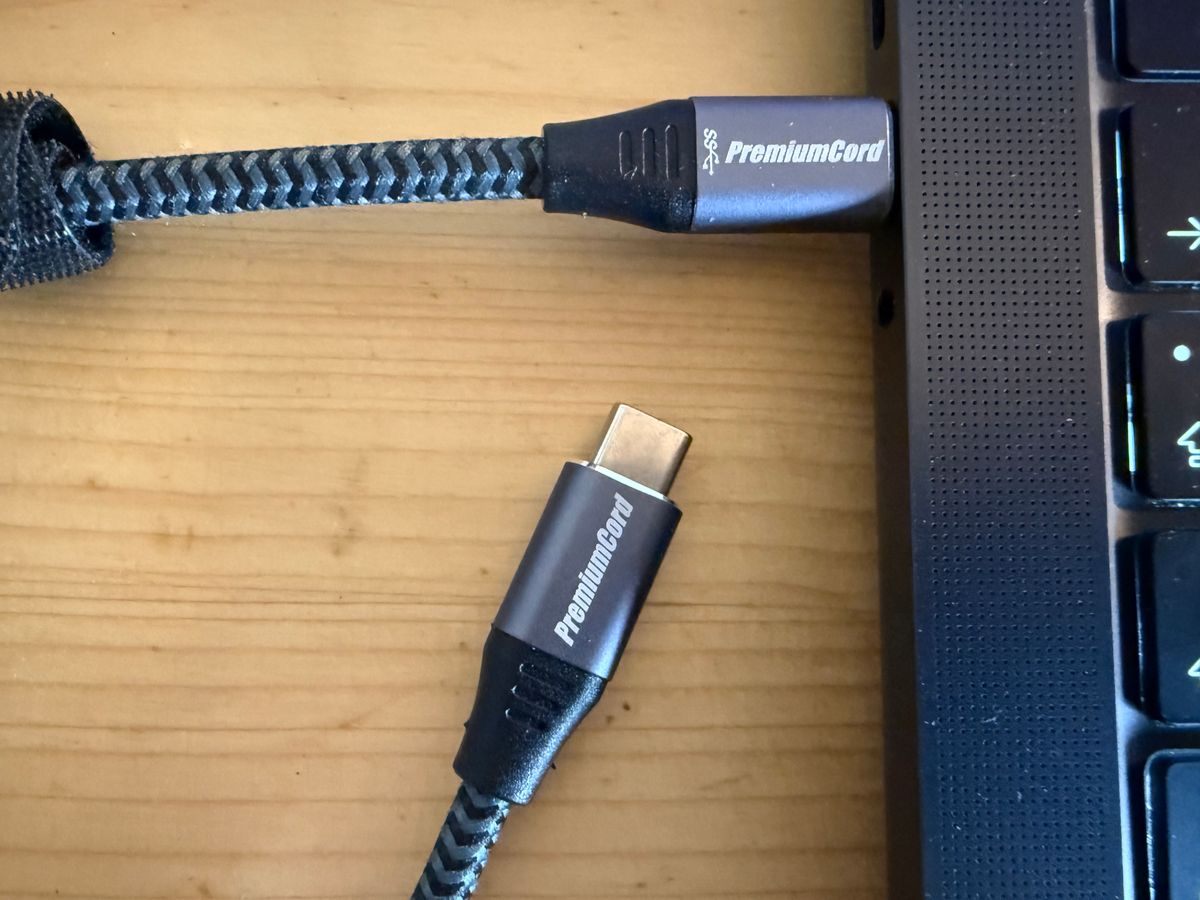
When I play with historical calculators—or, more recently, with my PAL-2 computer—I often need to connect a device with a serial port to a modern laptop. The UART side is still simple. The laptop side, however, has moved on to USB-C.
I already had a perfectly usable mini-USB-to-UART converter, but I no longer wanted to keep a mini-USB cable around just for that one board. A native USB-C converter seemed like an obvious and inexpensive upgrade.
The first one I ordered did not work.
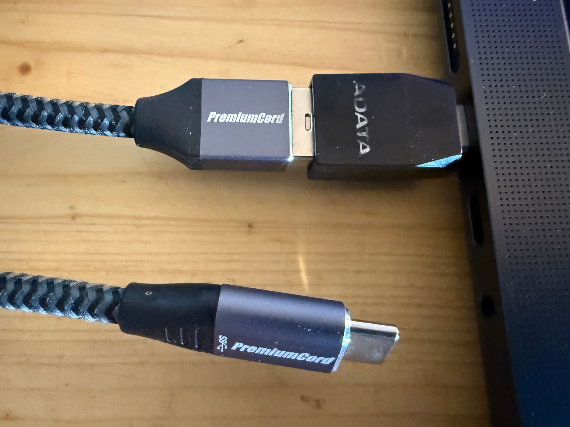
More precisely, it did not work when connected directly to a USB-C port. If I connected it through USB-A—or used the wonderfully absurd chain USB-C → USB-A → USB-C—the same converter appeared and worked normally.
The tiny components that make USB-C work
The problem is a common shortcut in cheap USB-C designs. A USB-C peripheral acting as a power sink is expected to present an Rd pull-down on both CC pins. A simple implementation uses a 5.1 kΩ resistor from CC1 to ground and another 5.1 kΩ resistor from CC2 to ground. These terminations tell the host that a device has been attached and allow it to determine plug orientation and enable VBUS.
If those resistors are missing, a proper USB-C source may see no valid sink at all and therefore provide no power. The USB 2.0 D+ and D− wiring may be fine, but the converter never gets the VBUS it needs to start.
The USB-A detour hides the mistake. A legacy USB-A port supplies 5 V without the Type-C CC attachment procedure, so the converter wakes up and its otherwise ordinary USB-to-serial circuitry works.
After the first failure I ordered a different design. It failed in exactly the same way. At that point I ordered several variants and decided to find out which ones were genuinely usable from a USB-C-only laptop.
How I tested them
I tested each board in two configurations:
- Direct: USB-C → USB-C
- Legacy detour: USB-C → USB-A → USB-C
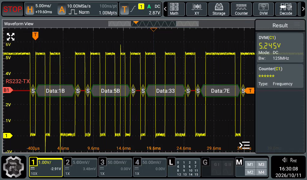
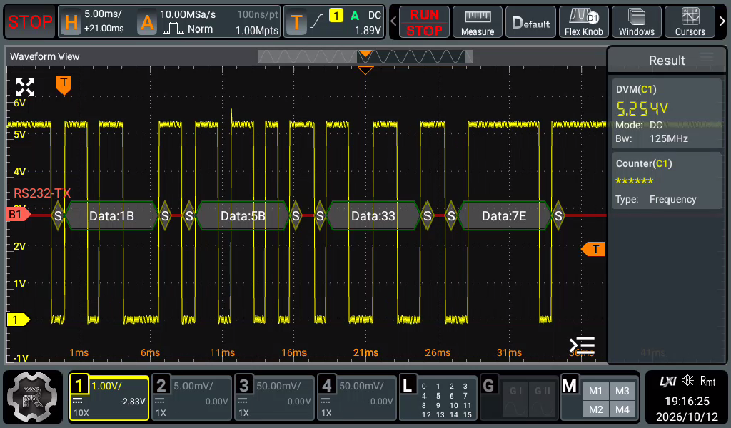
I recorded the USB identification reported by the operating system, measured the boards, and looked at the UART TX signal with an oscilloscope. As a repeatable example I pressed Fn-Backspace in the terminal. It sends the four-byte escape sequence 1B 5B 33 7E—that is, ESC [ 3 ~. The oscilloscope decoder shows the same four bytes in each capture.
| # | USB bridge | Size | Direct USB-C | Measured TX high/idle |
|---|---|---|---|---|
| 1 | CH3401a86:7523 | 24.7 × 13.7 mm | No | 5.245 V |
| 2 | CP210x10c4:ea60 | 20.8 × 15.6 mm | Yes | 3.524 V |
| 3 | CP210x10c4:ea60 | 22.7 × 15.4 mm | No | 3.373 V |
| 4 | CH3401a86:7523 | 32.2 × 13.3 mm | Yes | 3.290 / 5.533 V |
| 5 | CH340E1a86:7523 | Not measured by mistake | No | 5.254 V |
The voltage figures above are the DVM readings shown by the oscilloscope for the TX line in the captured test conditions. They are useful observations of these samples, not guaranteed specifications for every board sold under the same appearance.
Converter 1: CH340, but USB-C in shape only
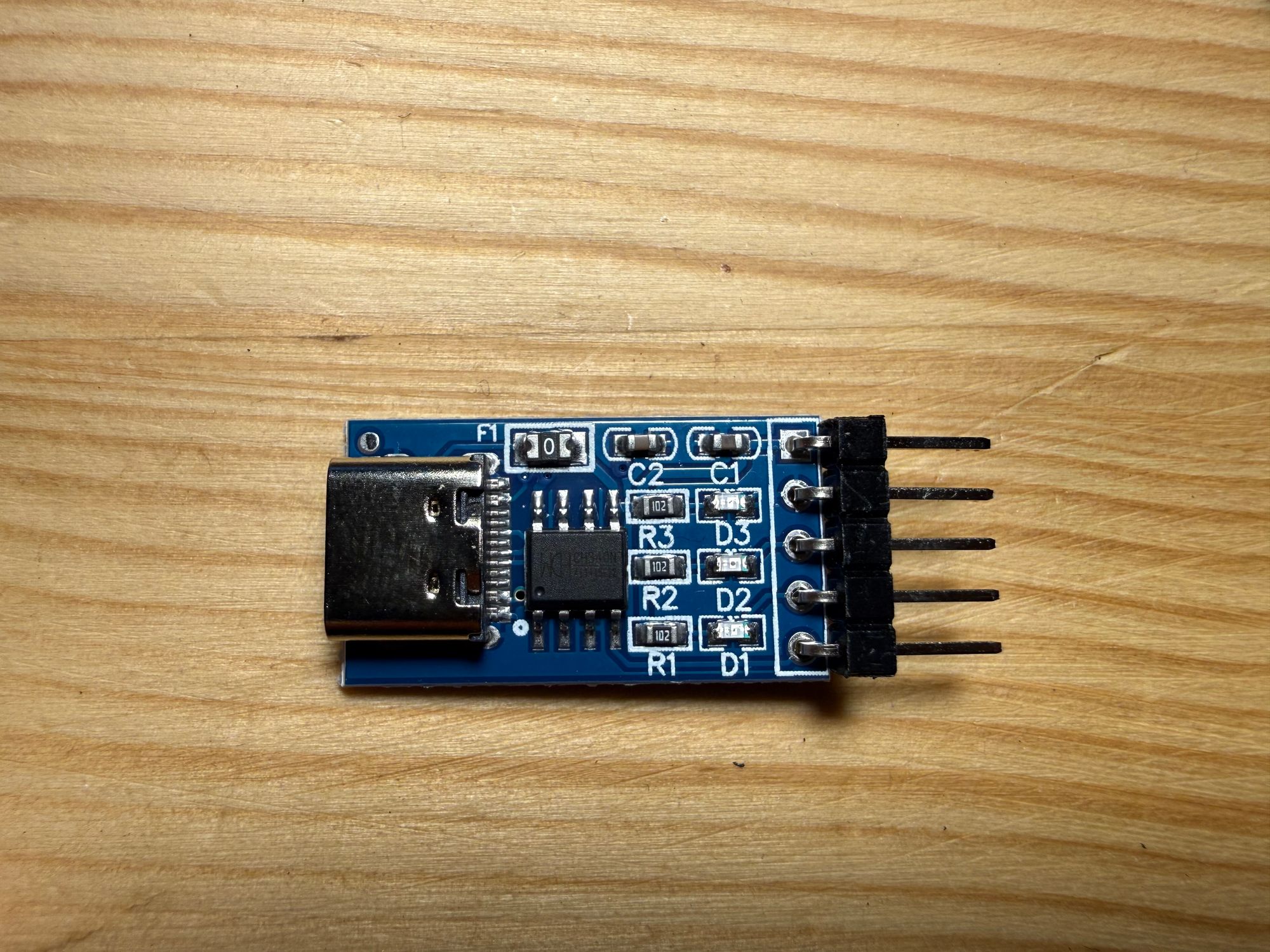
The first converter identifies as QinHeng Electronics CH340, USB ID 1a86:7523. It measures 24.7 × 13.7 mm.
It worked through the USB-A adapter chain, but not from a direct USB-C-to-USB-C cable. This was the board that started the entire investigation. Once powered through the adapter chain, its TX output decoded the expected four bytes and measured 5.245 V.
Converter 2: the smallest—and a proper direct connection
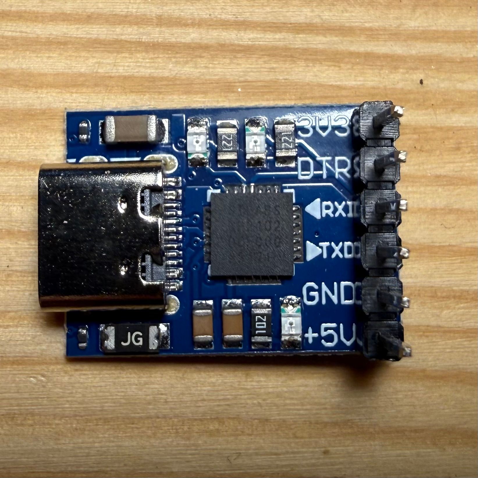
Converter 2 identifies as a Silicon Labs CP210x UART Bridge, USB ID 10c4:ea60. At 20.8 × 15.6 mm it is the shortest board in the test.
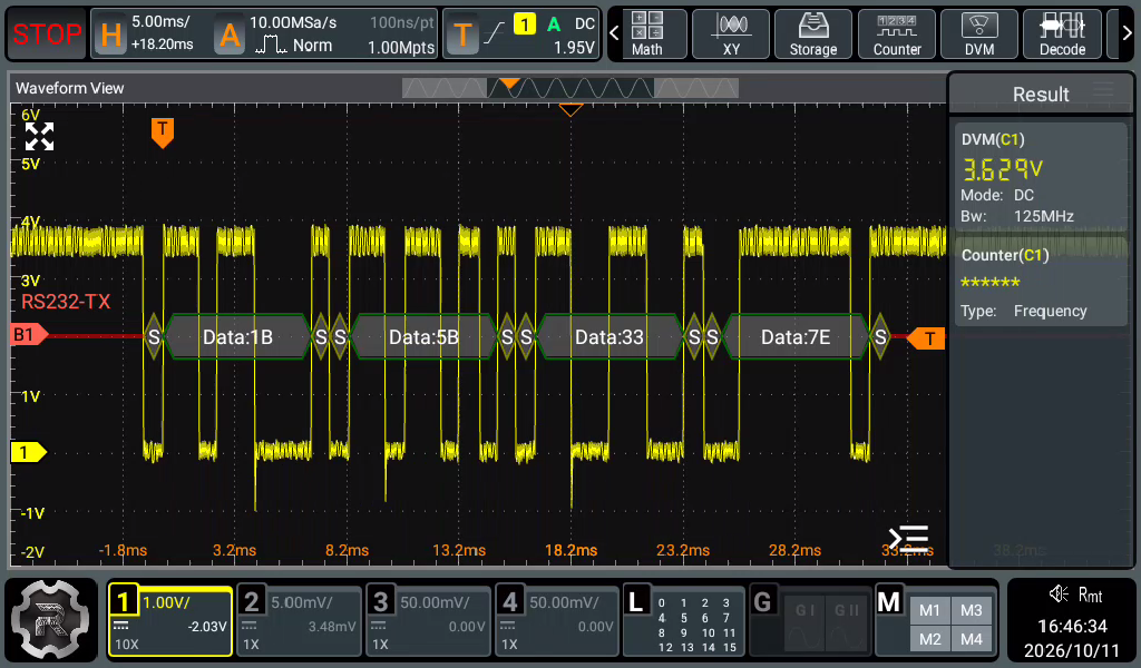
Most importantly, it worked with a direct USB-C-to-USB-C connection. Its TX capture decoded the expected 1B 5B 33 7E, and the scope's DVM showed 3.524 V.
Converter 3: almost the same, but missing the point
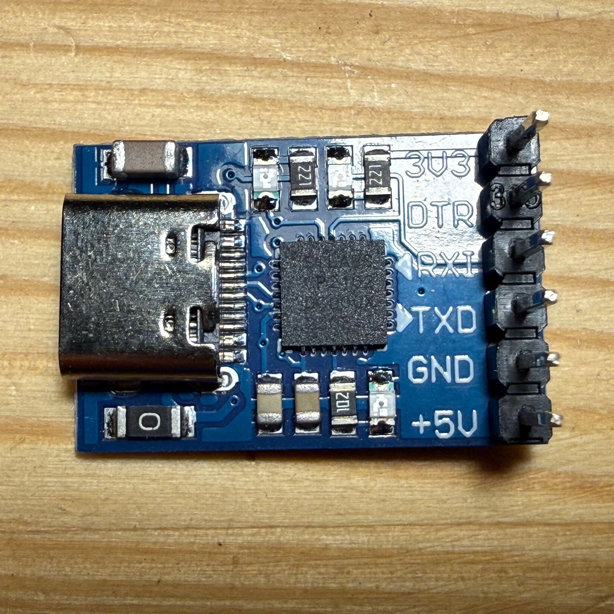
This board also identifies as Silicon Labs CP210x with the same 10c4:ea60 USB ID. It is only about 2 mm longer than Converter 2, measuring 22.7 × 15.4 mm.
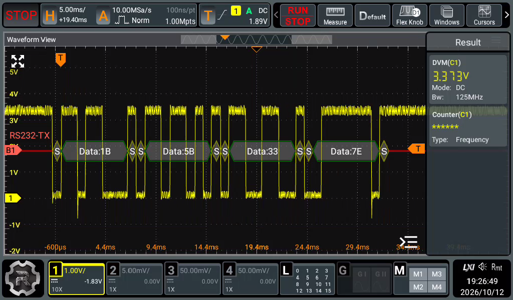
Despite the similar chipset and dimensions, it did not work directly over USB-C. It appeared only through the USB-A detour. Once powered, its UART output was fine: the four bytes decoded correctly and the DVM reading was 3.373 V.
Converter 4: the larger CH340 board gets USB-C right
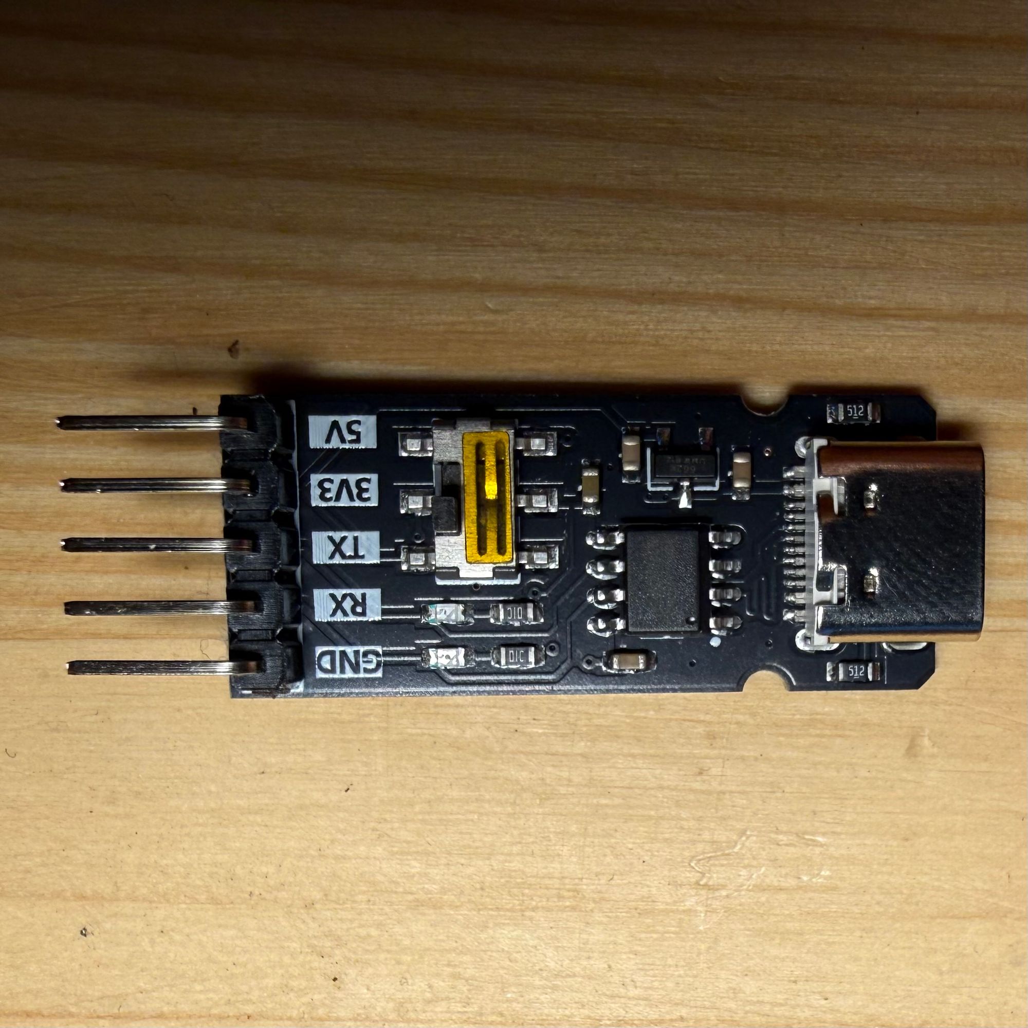
Converter 4 returns to the CH340 family and USB ID 1a86:7523. It is the longest measured board at 32.2 × 13.3 mm.
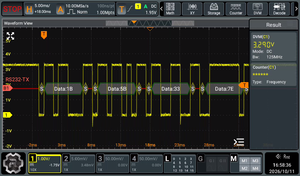
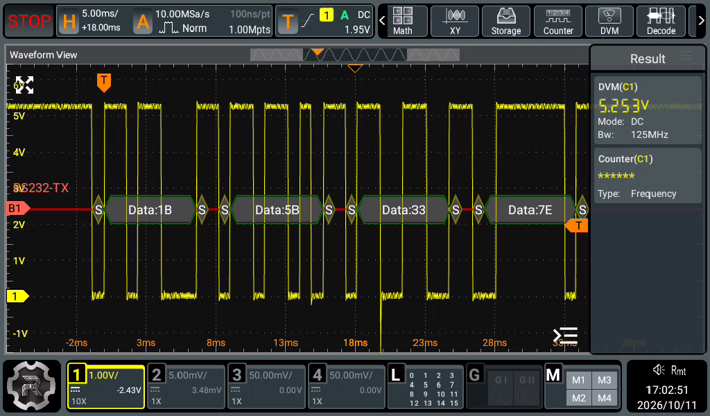
This one worked directly with USB-C. It also has a selectable UART output level, allowing operation at either 3.3 V or 5 V. Both captures decoded 1B 5B 33 7E; the scope's DVM readings were 3.290 V and 5.533 V.
Converter 5: CH340E, but no direct USB-C operation
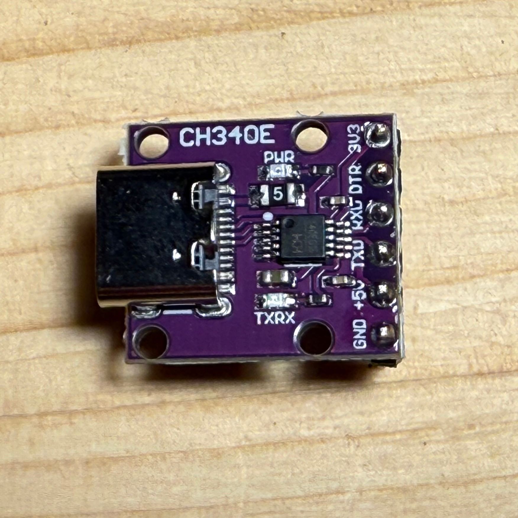
The fifth board is marked CH340E and enumerates as 1a86:7523.
Unfortunately, it failed the direct USB-C test and needed the USB-A adapter chain. Once powered, its scope capture decoded the expected four bytes and showed a DVM reading of 5.254 V.
The result
Out of five USB-C-to-UART converters, only Converter 2 and Converter 4 worked when connected directly to USB-C. The other three were functional USB-to-UART bridges hidden behind an incomplete USB-C implementation.
The chipset was not a reliable predictor. One CP210x board worked and another did not; likewise, one CH340 design worked while other CH340/CH340E boards required the adapter chain. The fault is in the surrounding board design—not in the UART bridge family printed on the package.
For a USB-C peripheral, the connector alone is not enough. If the board omits the two inexpensive 5.1 kΩ CC pull-down resistors, it may work from USB-A and still fail on exactly the modern USB-C-only computer it was bought for.
My practical winner is Converter 4: works fine and you can select voltage levels...